

Add-On Adventure
- Otter Robotics

- Mar 6, 2020
- 3 min read
The Add-On Port Adventure; an Otter Robotics story.

In order to complete the 7 different Pi Wars challenges using different equipment for each, we have chosen to use a 2-part add on system. This involves the use of different sensors and actuators that can be swapped in and out on a by-challenge basis.
The system we devised to do this started off with a 3D printed housing and metal contactors. This system was, unsurprisingly, far too fiddly for sensible assembly and ended up being horribly unreliable. Due to the flexible metal strip contactors, there is a high chance that, should we have settled on this design, it would have failed after just a few uses. After that minor failure, we investigated another design – utilising pre-made connectors. This was, in many ways, a poorer design than before as the 6 2-way connectors would not align without a lot of help. These connectors were also not the cheapest so the cost may have mounted up. While they were highly impractical, at least they made a colourful art installation.
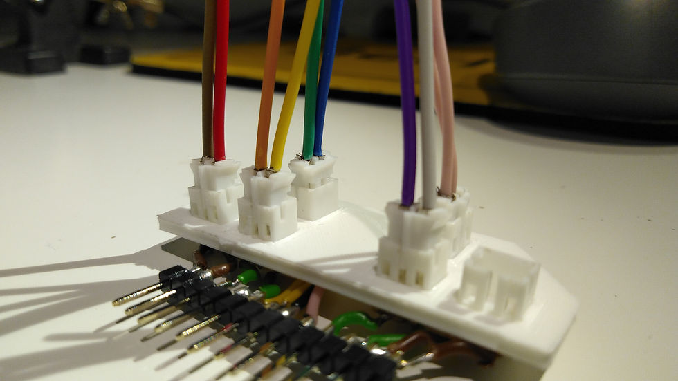
Unfortunately, colourful art is not going to win us Pi Wars so it was back to the drawing board for a final time.
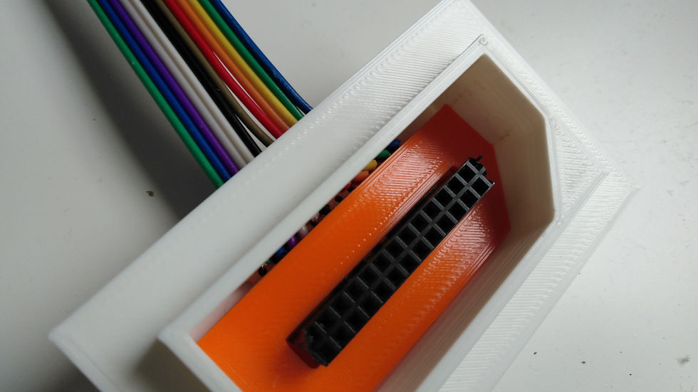
In the current add-on port, the receptacle construction is as follows. First, a 3D printed shell is created. This is a flat plate with an odd-shaped hexagon. There is a hole on the side for the connecting wires to escape to the Pi.
Inside the 3D printed shell, there is a piece of circuit board material that has a female 24 pin header on it. This circuit board section can then be screwed to the white PLA housing. An orange plastic cover then friction-fits into the housing to cover the circuit board. We selected the 24 pin header not because we need 24 pins but because it is what was to hand and thus, utilising just 12 pins, we have doubled up each column to give some built in redundancy. Each of the 12 pins has it own function on the robot and their use is shown below. 4X ID pins to tell the pi what add on is connected to the socket. 3X GPIO pins for more simple add ons, 2X Power pins to provide 3.3v power from the Voltage regulator onboard and 2X I2C pins to provide an expansion opportunities for more complex add-ons; these could possibly utilise an Arduino Pro Mini Co-Processor. By using a connector such as this, we hope to be able to quickly swap new hardware in and out for various challenges; we also hope that it can assist the speedy development of further add-ons as required, which, at the current stage of the competition, is paramount. Due to the add-on being located in the middle and the fact that many of the add-ons are simply too heavy to be supported by the pin’s friction, some of our add-ons make use of a second physical attachment. This is mounted to the front of the robot with screws and looks like this:

This simply allows for a strong, secure and easy connection on the front of the robot: on the other hand, it is a shame that I am yet to make a receptacle connector that fits correctly in all three holes. On the software side, I have created a python module that handles low-level interface with the add on in order to allow for quick incorporation of new add-ons and easy access to important parameters such as the input pins etc.
The connector to plug into this port has also been meticulously designed. It is, again, 3D printed with the current revision coming in 3 3D printed parts plus some extra circuit material etc. The below image aught to help illustrate this point.
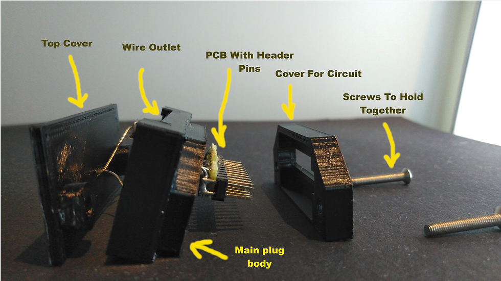
This design has the advantage of being fairly low profile, requires little effort to replicate and can provide a solid connection to the robot.
Thank you for reading this information about the add-on port, be sure to check back in for posts on different add-ons we have made.


Comments